Welcome to Kaifeng Ruike Valve Co., Ltd.
Categories
Contact
E-mail :
rkvalve@vip.163.com
Tel:
86-371-27565515
Address:
West section of Fuyuan Road,Yushi County Industrial Clustering Zone


DN1200 Pneumatic Butterfly Vapor Suction Check Valve
Categories:
Check Valve
Product Model:
Calibre Range:
Pressure Rating:
Operating Temperature.
Main Body Material:
Connection Method:
Mode of Operation:
Application Industry:
Product Details
I. Application
This pneumatic butterfly type steam pumping check valve is installed in the steam pumping horizontal pipeline leading from the low-pressure steam guide pipe in the turbine, mainly to prevent the steam in the pumping pipeline from backing up in case of accidents, which may cause the turbine to overspeed.
Characteristics
1、The valve adopts the structure type combining independent check valve and auxiliary pneumatic shut-off device (the gas source is provided by the user).
2、The valve seat adopts large oblique angle to shorten the opening and closing stroke and reduce the impact of the valve plate on the valve seat.
3、The butterfly plate adopts three eccentric sealing structure, the opening seal is separated, the closing contact is sealed, opening and closing is light and flexible.
4、The sealing surface between the valve seat and butterfly plate adopts 13Cr surfacing for the valve seat, and the sealing ring of the butterfly plate is 20Cr13+nitriding, which has good performance of anti-abrasion and anti-water corrosion, so that the valve can maintain good sealing for a long time.
5、When the turbine starts to work, the gas source in the control system device enters the lower cavity of the shut-off cylinder through the electromagnetic reversing valve, which pushes the piston of the shut-off cylinder upward, compresses the spring and makes the spring store energy, and the butterfly plate opens under the push of the pipeline medium. When the system fails, the pressure of pipeline medium decreases, the butterfly plate closes under the action of its own gravity, at this time, the control system gas supply solenoid reversing valve accepts the signal to change the direction of the gas source, so that the gas into the lower chamber of the shut-off cylinder quickly discharged, the shut-off cylinder upper chamber spring quickly extends to promote the downward movement of the cylinder piston, to help the butterfly plate to the fastest possible closing speed, the valve in the butterfly plate closure from the store to help the power device to obtain a certain locking The valve gets a certain locking force from the power device after the butterfly plate is closed to prevent the backflow of steam and condensate in the pipeline system and protect the turbine and other major equipment.
6, the valve actuator adopts gas-open type, once the solenoid valve is de-energized, the valve should be closed quickly, the time from fully open to fully closed is less than 1 second, the emergency cut-off is safe and reliable.
7, the installation of auxiliary power unit does not affect the reliability of the valve, once the auxiliary power unit failure, the valve can still use the butterfly plate under its own weight and the role of the reverse steam flow to close itself.
8, the valve is set to open and close the position of the travel switch, and can be transmitted to the operation of the centralized control room to facilitate timely understanding of the state of the valve operators, but also set up in situ mechanical valve position indication.
9, the scope of supply: each valve with actuators, manual test ball valves, gas source processing triple (with pressure gauge type), solenoid valves, quick-exit valves, travel switches.
Third, the technical requirements
1、Gas source interface: RC3/8
2、Cylinder operating pressure: 0.4~0.8 MPa
3、Emergency cut-off time: ≤ 1 second
4、Power supply voltage: AC220V
Design selection standards
1、Design in accordance with the provisions of GB/T12236;
2、Flange according to the provisions of GB/T9113;
3、Welding end in accordance with the provisions of NB/T47044
4、Pressure and temperature levels according to the provisions of GB/T12224;
5、the pressure test of the valve according to the provisions of GB/T13927;
Installation and maintenance
1. The valve should be stored in a dry, ventilated room, the valve channel ends should be blocked.
2. Long-term storage of the valve should be regularly inspected to remove dirt. Special attention should be paid to the sealing surface of the clean, anti-sealing surface damage.
3. Add appropriate amount of lubricant to each friction surface of the shaft and bushing.
4. Coat the inner surface of the sealing ring with grease film.
5. The valve installation direction according to the medium flow direction and the valve body arrow consistent.
6. When the pipeline is tested for strength, pressure should be applied in the direction of the arrow of the valve body.
7. The products of this factory are qualified by strict test before leaving the factory, please do not unscrew the parts of the product.
8. The valve channel and sealing surface should be checked before installation. If there is any dirt, it should be wiped clean with a clean cloth.
9. Before installation, check whether the packing is pressed tightly, it should ensure the sealing of the packing, and at the same time, it should not hinder the rotation of the valve stem.
10. When lifting the valve, the rope should not be tied to the handwheel or stem to avoid damage to these parts, but should be tied securely to the valve body through the lifting lugs (if any) or by tying the rope firmly to the valve body.
11. When installing, flange connection valve tightening connecting bolt tightening force should be uniform and appropriate, using the cross method to tighten all bolts. Valve flange and pipe flange must be parallel, reasonable clearance, so as to avoid excessive pressure on the valve, or even cracking.
12. Butt-welding end of the valve installation welding to prevent welding slag into the inner cavity of the valve, damage to the sealing surface; in the preheating, welding or post-welding thermal stress relief, from the weld 75m away from any point on the valve body at the temperature can not exceed 400F (200 ℃).
13. When installing, the pair of flanges on the pipeline and the valve flange to keep centering installation, so as to avoid the valve to withstand additional external forces, affecting the performance of the product, the pair of flanges should be welded to the pipeline before connecting with the valve, butterfly valves are not allowed to weld the flange after mounting.
14. Valve by the test run, to confirm that there is no error before being put into operation.
15. Some valves must also have external protection, such as; insulation or cold.
16. Valve use should be regularly checked, check the sealing surface for wear and gasket packing. If the damage failure, should be promptly repaired or replaced.
Blueprint
Parameters
Main technical parameters
|
DN( mm) |
100~1600 |
||||||
|
Nominal Pressure( MPa) |
0.6 |
1.0 |
1.6 |
2.5 |
4.0 |
6.4 |
|
|
trial pressure |
Strength test |
0.9 |
1.5 |
2.4 |
3.75 |
6.0 |
9.6 |
|
Seal test |
0.6 |
1.0 |
1.6 |
2.5 |
4.0 |
6.4 |
|
|
Applicable media |
Water, steam, gas |
||||||
|
Applicable temperature (°C) |
Soft seal: ≤80°C; C carbon steel -29-425 ℃; I alloy steel -29-530 °C; P Inconel Steel vs. R Inconel Titanium Steel -196-600 °C |
||||||
Main component material
|
numbering |
The name of the component |
Material Description: |
numbering |
The name of the component |
Material Description: |
|
1 |
Valve body |
Q355B+D507 |
5 |
Stem |
20Cr13 |
|
2 |
Seals |
20Cr13 nitride |
6 |
stuffing |
Flexible graphite |
|
3 |
Butterfly plates |
Q355B |
7 |
bracket |
WCB |
|
4 |
Axle rod |
20Cr13 nitride |
8 |
Pneumatics |
Assemblies |
Possible malfunctions and ways to eliminate them
|
Fault phenomenon |
Cause of the failure |
Elimination method |
|
Pneumatic actuators are not flexible in action |
1 Control line failure 2 The solenoid valve coil is burned out 3. Failure of air supply |
1. Check the control line 2. Replace the coil 3 Check the air supply |
|
Leakage at the filler |
1. The packing gland nut is loose
2. The packing is damaged |
1. Tighten the gland nut (subject to no leakage at the packing place) 2. Change the packing |
|
Leaks at the covers on both sides of the valve |
1. The sealing gaskets of both sides of the cover fail 2. The compression force of the pipe flange is not enough or the compression is uneven |
1. Replace the sealing gasket 2. Re-compress the flange bolts |
|
Leakage of the sealing surface |
1. There are debris on the sealing surface of the valve disc 2. The valve disc is not closed in place 3. Scratches on the sealing surface |
1. Eliminate impurities and clean the inner cavity of the valve 2. Twist the connecting nut to adjust the gap between the valve stem and the piston rod 3. Grind the sealing surface |
Key words:
Check Valve
Previous:
Next:
Company Information
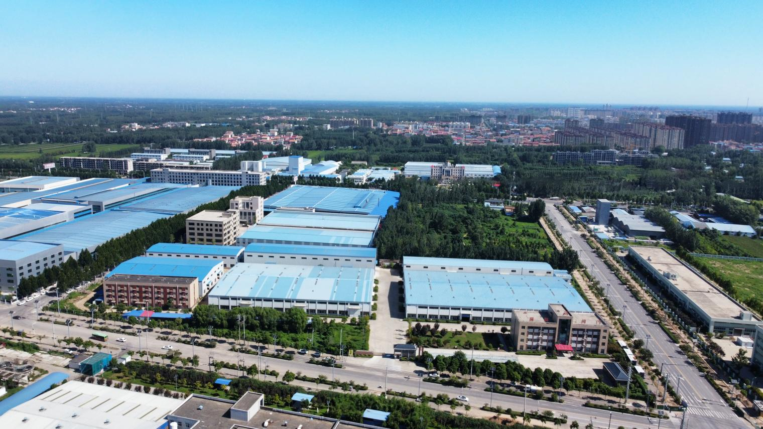
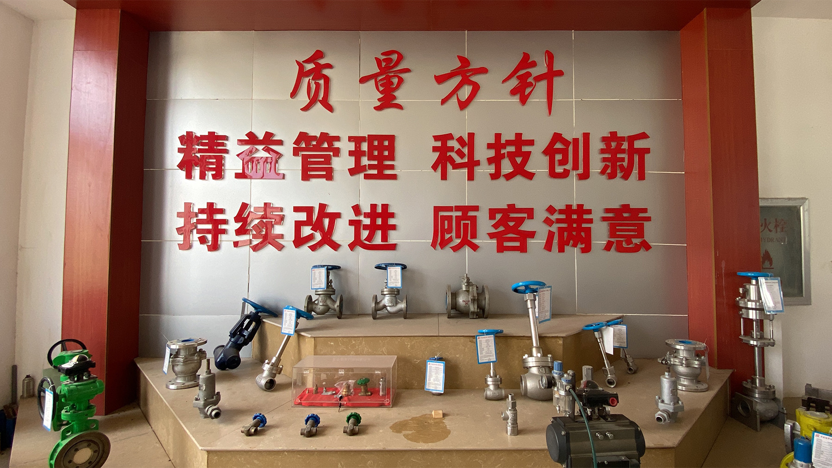
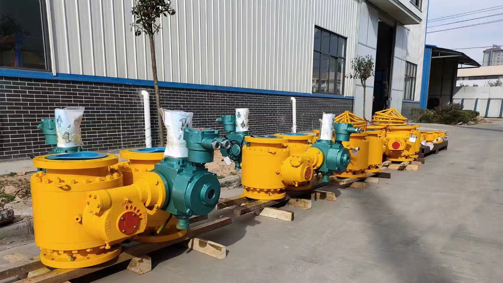
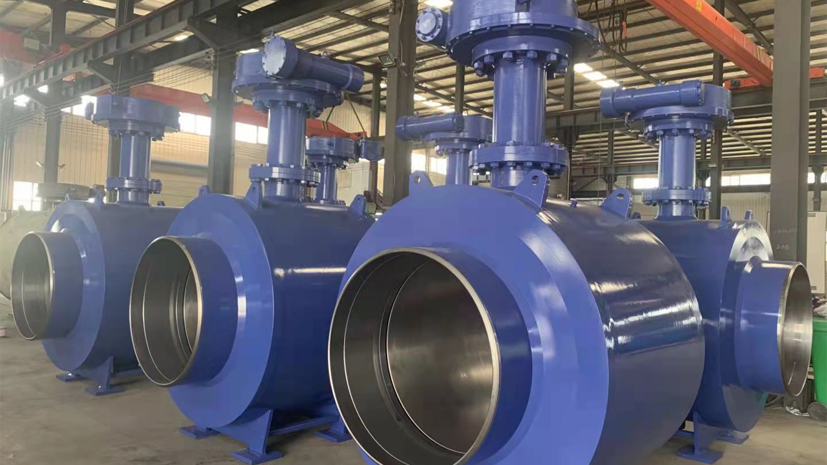
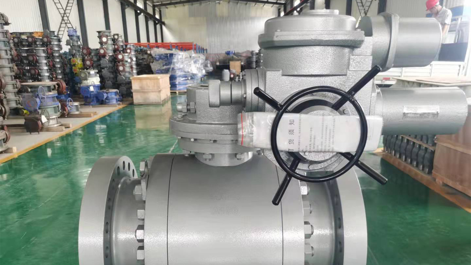
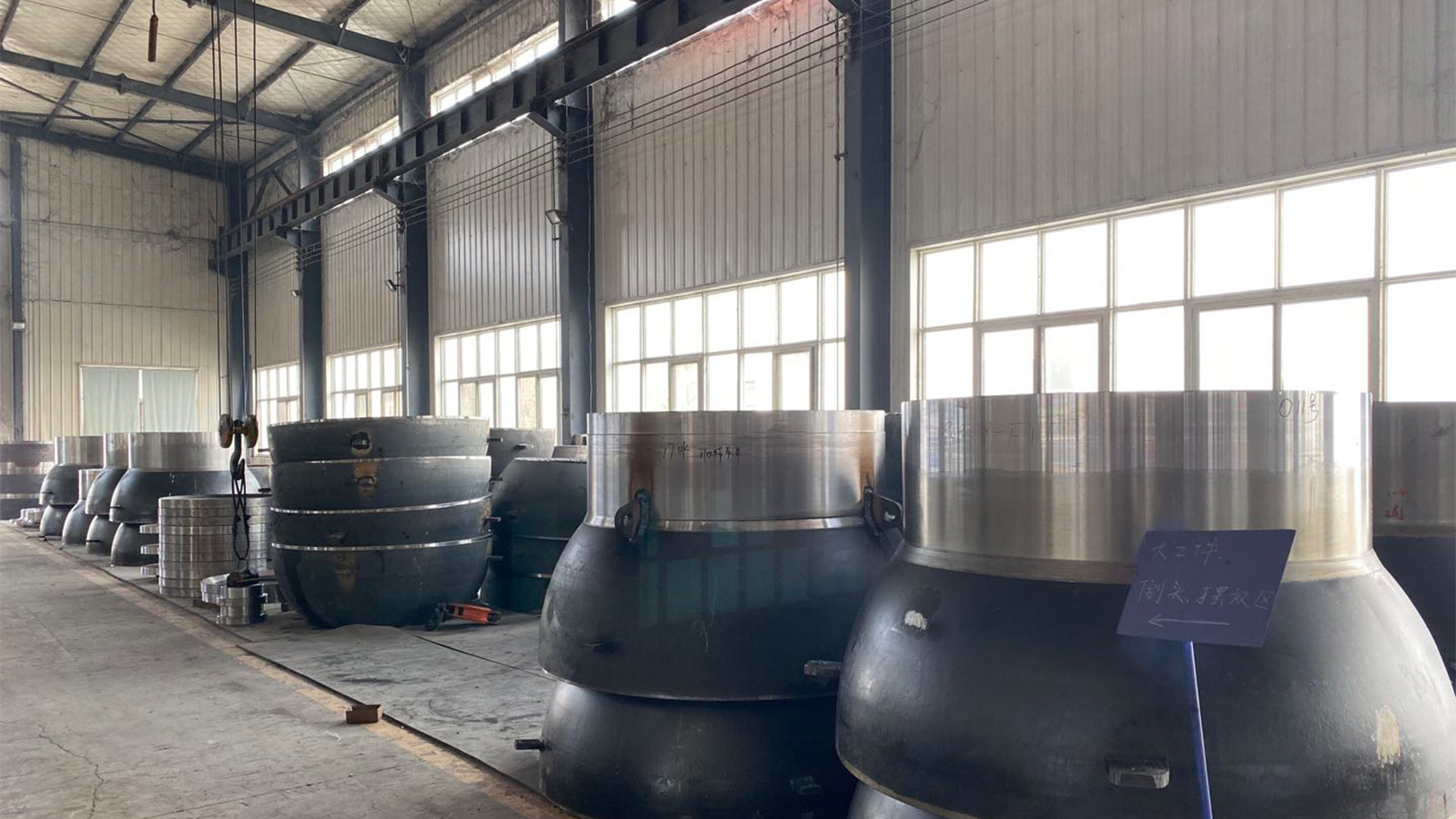
Kaifeng Ruike Valve Co., Ltd. has developed into a joint-stock enterprise integrating valve research, development, production and sales. Founded in 2011, the company covers an area of 52,000 square metres. There are more than 136 employees, 45 technicians of various types, including 4 professor-level senior engineers.
The company now has CNC machining centres, CNC machine tools, large vertical lathes, large boring machines, CNC milling machines, automatic welding machines and other sophisticated machining equipment, and high-performance valve testing equipment more than 100 sets (sets). Set up semi-finished goods warehouse, finished goods warehouse and so on.
FAQ
Do you accept custom design on size?
Yes, if the size is reasonable.
Do you provide free sample?
Free sample is OK for us.
Transportation
Transported by DHL, UPS, EMS, FEDEX, SF, by Air, by Sea.
Payment
T/T, L/C, OA, D/P, D/A.
After-sales service
18 months year warranty for all kinds of products.
As an experienced manufacturer, you can rest assured of the quality and sales service.
What certificates will you provide ?
We can provide CE/ ISO / WRAS.
Related Products
API6D cylindrical fixed flange ball valve
API6D cylindrical fixed full-welded underground ball valve
API6D Ball Type Fixed Full Welding Ball Valve
API6D Cylindrical Fully Welded Fixed Ball Valve

